Another home automation post! Please check out my earlier home automation series first to get an idea what I am talking about.
Recently, I figured to rework some part of it to be able to deal better with certain kind of failures, while at the same time still being able to offer all the automation abilities as before.
Recap
First, let’s recap the architecture that was already in place:
- inputs: a unipi unit is used to read the digital inputs (e.g. push buttons); updates are pushed as MQTT events
- MQTT broker: a centralized broker takes in the updates and pushes them to all subscribers
- home assistant: sees updates on the MQTT inputs and performs specific actions as automations on outputs push out another MQTT events
- outputs: a unipi unit takes in MQTT updates and triggers a corresponding relay change (e.g. a light).
For more details, refer to the architecture post.
Although this approach has worked fairly well for me, it inherently holds some potential issues.
Problem: centralized points of failure
Firstly, on the software level, all connections need to run through home assistant and the MQTT broker. An advantage of this is that everything is configurable from a centralized place, in software. However, this also requires a higher level of reliability on those software instances. As an example, initially, doing any updates to this software component was a bit more involved since any downtime here, effectively translated into non-functioning light push buttons. Downtime is fortunately a lot less common since I did start using k3s for orchestrating the deployment. Nevertheless, it is (currently) not possible to run home assistant in an “high availability” (HA) mode. HA mode means that multiple home assistant instances can run at the same time, where one instance sits idle as a fail-over for the main running instance.
In addition, on the network level, the links between the components all depend on the local network. Any downtime at this level of the stack again translates into the non-availability of my light push buttons.
This solution would need to be more robust against issues on both software and network layers. At the same time, I would still like to keep centralized control from home assistant.
Solution: direct link
I did start digging around and got some helpful feedback on the unipi forum from this post on connecting 2 unipi units together.
The first issue of the dependency on the home assistant instance could be mitigated by moving the automation logic out of home assistant. This would mean that some other component could listen to the input events and do the required actions on the outputs. The unipi units could easily run such extra software themselves.
The second issue related to the network layer could be solved by finding a way to connect to the involved unipi units directly together. This post on unipi connections provided some inspiration in that respect: the third option details using the RS-485 bus which is available on most unipi units to connect devices together.
Control from home assistant will still be possible: either the update should come from the toggle of an input button (via the direct connection) or from an MQTT event. There should be no issue in having both options at the same time.1
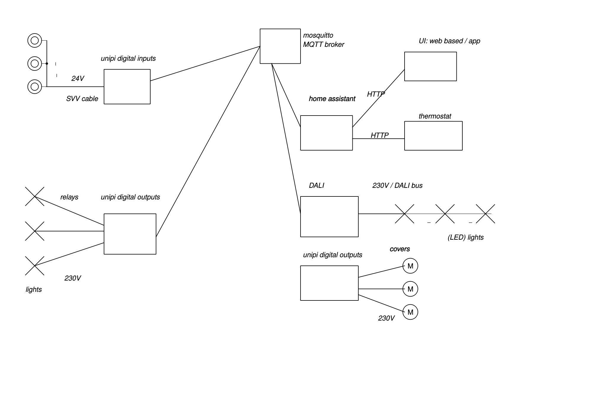
The new architecture now changes into the following:

- inputs / outputs: the edges of the diagram just again show the inputs and output
- unipi units: 1 unipi unit is shown for inputs, 1 for outputs
- home assistant: state updates on inputs and outputs still come in over MQTT. State changes on the outputs can still be pushed using MQTT.
- MQTT broker: sits between the unipi units and home assistant.
The key difference over the previous architecture is that the link between the input push buttons and the output relays is no longer established using an automation in home assistant. Instead, there is a direct link over RS-485 using the Modbus protocol.
Hardware
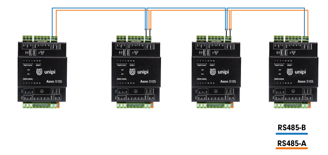
The following image (taken from the post on unipi connections) shows a conceptual wiring diagram to connect one or more unipi units together. Essentially, it is a 2-wire connection, daisy-chaining all units.
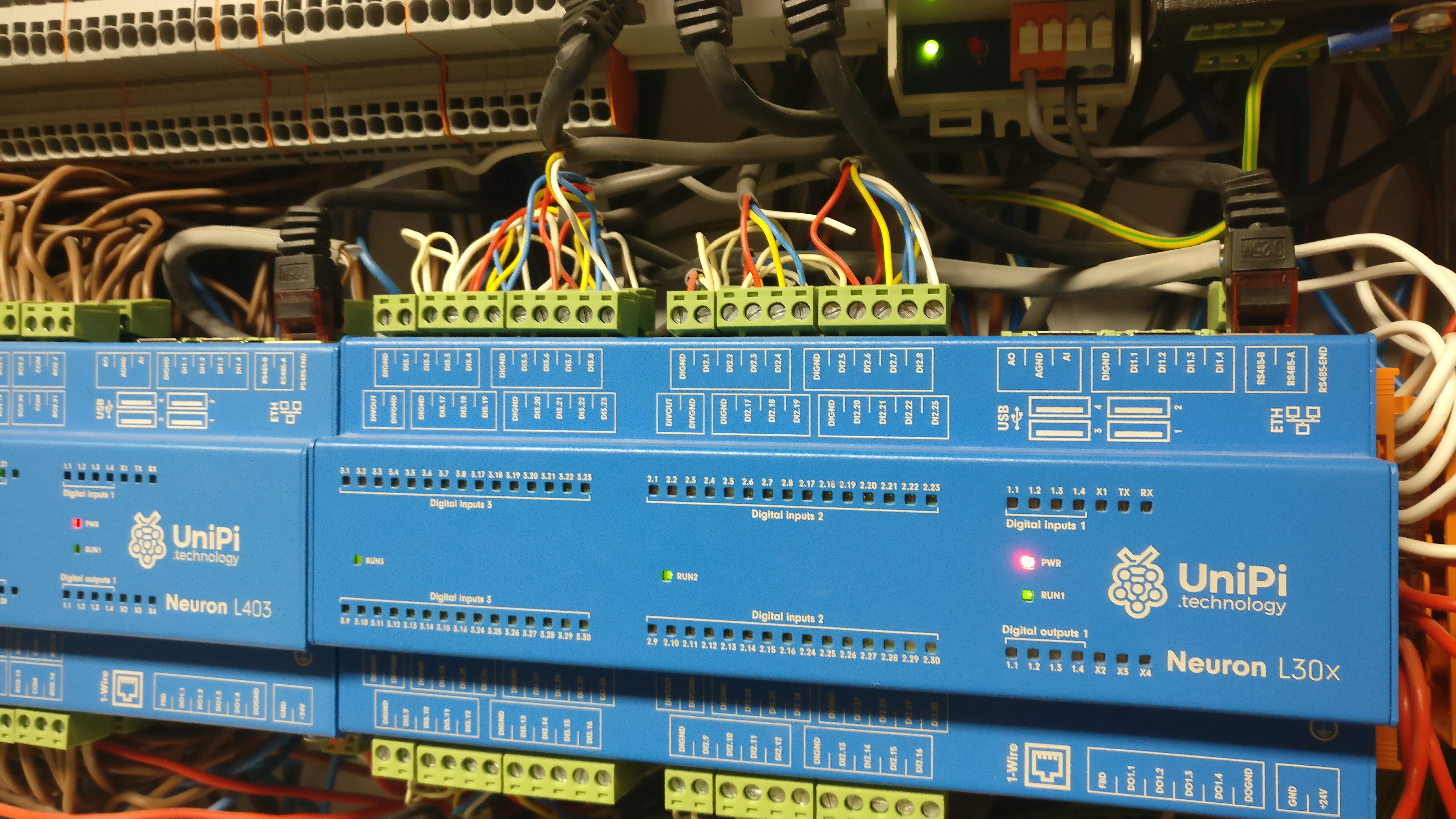
As the photo shows, the wiring I did use was a simple piece of leftover CAT6 UTP (the grey piece of cable behind the black ethernet connector in the front). In fact, I only did use 2 of the 8 wires.
For my purposes I only did connect 2 units together, but you could in principle extend this over to multiple clients on the same bus. This would practically mean extending the 2-wire connection from the last connection on.
I did not need to introduce any additional resistors nor change any of the DIP switches, this all worked fine out of the box.
As the unipi units readily expose the RS-485 interface, this step turned out to be really simple.
Software
The protocol you would typically run on this wiring setup is Modbus. Within Modbus, there is one server and all the other clients are daisy-chained on the same bus. All clients provide their own set of inputs and outputs (“coils”, “discrete inputs”, “input registers” and “holding registers”) in a predefined range. Read and write control is fully managed by the server. To read specific values, the server will just poll those values from the client. To write updates, the server can similarly just put the values where they need to be on the clients. The speed at which updates from a client are propagated thus also depend on the polling speed the server uses. In case any communications needs to occur between clients, this is only possible from the server. The server would then first read those values from one client (by polling) and later on write them to the other client.
The unipi OS exposes the RS-485 connection via a specific linux device; see the unipi serial port map.
For my neuron L403 and L303 I would need to use the /dev/ttyNS0 devices.
Running a Modbus protocol stack on both the client and server devices was however not provided by default by unipi.
Here I did write my own small script modbusbackup.py, which can run both in client and server mode.
The idea is to run a Modbus client (server mode) on the device that will be expecting incoming Modbus requests. A Modbus server is ran (client mode) on the device that sends out Modbus messages.
The implementation itself is based on PyModbus, which makes it possible to easily write both client and server code.
For now, I only implemented this connection between my unipi unit that reads my push buttons and the unipi unit that controls relays connected to lights. To illustrate, let’s again go through toggling a light:
- push button is pushed
- evok detects the push button change and exposes the event through a websocket event (among others).
- the
modbusbackup.pyclient (on the inputs unit) sees the websocket event, maps it our own configured Modbus address and sends it out as a Modbus message - the
modbusbackup.pyserver (on the relays unit) sees the incoming Modbus message, and translates it to the correct relay update; the current relay state is first retrieved (evok REST API) and then toggled. - evok handles the relay update
- the relay is toggled; the light is turned on
Client code
The key function is ws_process:
async def _ws_process(payload) -> None:
    """Process incoming websocket payload, push to modbus RTU"""
    obj = json.loads(payload)[0]
    # Ignore analog I?O
    if obj["dev"] in ("ai", "ao"):
        return
    logger.info(f"Incoming message for websocket {obj}")
    # Don't send any events related to trailing edges
    if obj["value"] == 0:
        return

    try:
        address = _circuit_map()[obj["circuit"]]
    except KeyError:
        logger.debug(f"Could not find mapping address for {obj['circuit']}")
        return

    # Blocking sync call
    logger.info(
        f"Writing {obj['value']} to address {address} for circuit {obj['circuit']}"
    )
    _modbus_client().write_coil(address, obj["value"], unit=_UNIT)
The function takes a payload from a websocket event, made available through evok. The reason we use a websocket event here is that it is easier to check any updates from the inputs as opposed to polling ourselves. Additionally, evok already exposes the events using websockets. This is part is quite close to the earlier solution presented in the software post.
The circuit_map function is singleton wrapper around a dictionary mapping the unipi digital inputs to Modbus addresses.
Similarly, the _modbus_client function is also a singleton wrapper to avoid having to constantly recreate the Modbus connection to the other unit.
See this link for the full client code.
Server code
The key to get this to work for me was having a Modbus instance being able to accept incoming messages and handling those directly, i.e. in an event-based way. After digging through some PyModbus examples, I did find this callback server example. I did end up with the following set of functions, definitions:
class CallbackDataBlock(pymodbus.datastore.ModbusSparseDataBlock):
    """callbacks on operation"""

    def __init__(self) -> None:
        super().__init__({index: 0x0 for index in _relay_map().keys()})

    def setValues(self, address: int, values: typing.List) -> None:
        logger.debug(f"Got {values} for {address}")
        _trigger(address, values[0])
        super().setValues(address, values)


def _run_server(port: str, timeout: float, baudrate: int) -> None:
    block = CallbackDataBlock()
    store = pymodbus.datastore.ModbusSlaveContext(
        di=block,
        co=block,
        hr=block,
        ir=block,
        zero_mode=True,
    )

    context = pymodbus.datastore.ModbusServerContext(slaves=store, single=True)
    pymodbus.server.sync.StartSerialServer(
        context,
        framer=pymodbus.transaction.ModbusRtuFramer,
        port=port,
        timeout=timeout,
        baudrate=baudrate,
    )
The _run_server code wraps starting up a serial, RTU, Modbus server.
The port to be provided to the server is simple the Linux device mentioned above, /dev/ttyNS0.
As part of a Modbus server configuration, you need to provide the outline of the various Modbus addresses it exposes for the main Modbus instance to poll.
In this, case I did pass in a custom block, the CallbackDataBlock.
The CallbackDataBlock constructor sets up all required addresses based on the configuration (through the _relay_map function).
The _relay_map function keeps a (singleton) mapping of the relays for the given Modbus address.
In order to have callback-like handlers, you can override the setValues method.
This method is called for any Modbus message for the address that is part of the function arguments.
At this point, I do have the message handled by another _trigger function.
def _trigger(address: int, value: bool, host="http://localhost") -> None:
    """Process incoming event"""
    # Only check for rising edges since we're dealing with lights
    if not value:
        return

    # Convert address to zero-based address
    try:
        relay = _relay_map()[address]
    except KeyError:
        logger.debug(f"Could not find relay for address {address}")
        return

    try:
        response = _session().get(f"{host}/json/relay/{relay}")
        response.raise_for_status()
    except requests.exceptions.HTTPError as error:
        logger.debug(f"Issue with API call: {error}")
        return
    try:
        current = response.json()["data"]["value"]
    except (KeyError, ValueError):
        logger.debug("Error reading current state")
        return

    # Flip the bit from current by XOR
    toggled = current ^ 0x1
    try:
        _session().post(f"{host}/json/relay/{relay}", json={"value": str(toggled)})
        response.raise_for_status()
    except requests.exceptions.HTTPError as error:
        logger.debug(f"Issue with API call: {error}")
        return
    else:
        logger.info(f"Toggled relay {relay} to {toggled}")
The _trigger function simply takes in the Modbus message and maps it again to a relay on the unipi output device.
For the purposes of light control, a simple toggle is enough, so the value is just used to see if the incoming event is actually for a rising edge, i.e. a True value.
The current value is read first using evok; the new value is the toggled value (by XOR).
Refer to this section for the full server code.
Configuration format
As configuration format, I did use YAML, similar to what I had before on home assistant. The source code repository also holds a sample configuration file – actually, my configuration file. The format looks like this:
- index: 0
  input: "2_03"
  name: kelder inkom inbouw
  output: "2_01"
The index can be an arbitrary number – yet it needs to be unique.
The input relates to the digital input on the unipi unit connected to the inputs.
Similarly, the output relates to the relay output on the other unipi unit.
The name field is just there for documentation purposes.
The automation part previously handled by home assistant now effectively becomes part of this configuration file.
The link between input and output is done by the unique index field.
The input-side will map its digital input change to the index; this index is used as Modbus address.
On the other end, the output-side will map the incoming Modbus address to the its relay it needs to change.
This also means that this configuration file needs to be shared between both the input and output side.
Closing thoughts
While my home automation setup described in the home automation series has been running OK for me for quite some time, I did want to be less dependent on the correct functioning of the home assistant instance and the network.
To get there, I made changes on 2 levels. On the hardware-side, I did make use of the already existing RS-485 connection, removing any network-related issues. On the software-side, I did add a custom script to run on both the input and output side that essentially notifies the output-side of any input-related events. The actual link between the input and output is through a simple configuration file, shared by both sides.
I only did implement this connection for my lighting setup since I did feel this is the most critical part for me to continue to keep on functioning. For my alarm setup and my shades, all input and outputs are actually each on their own, same unipi unit. This means that in order to decouple those from home assistant I could also write some custom code, but they would not need the whole RS-485 connection, nor any Modbus setup.
Note that some push button-to-light connections still go through home assistant: I have e.g. some Philips Hue lights that get triggered via a push button change. For this case, I think it still makes sense to keep this connection in home assistant. However, once I would start to expand my DALI-bus based setup, I’m not yet sure how to tackle this.
The transition between the fully home assistant-based outline and my current “modbusbackup” solution has gone pretty well though, to that extent that it’s not really clear to others in my home what I have actually been working on. The main advantage I now see is being able to more easily make any changes on the home assistant / network side.
the automation that was already in place in home assistant to link input to output would need to be removed though. ↩︎