In earlier posts, I did provide an overview of the architecture of my custom-made home automation system. I also did describe some specificities related to a wired home automation setup. For my system, I decide on wiring everything in a star-configuration, meaning all wiring around the house for lights, push buttons, … all converges in a centralized electrical cabinet. The focus of this post is to show you some details of what this cabinet looks like and some pointers for practical issues I had run into.
This post is a part of a larger series of posts on my home automation setup. See the home automation overview post, to learn about the rationale and a description of the other posts!
Inside the cabinet
Given the star-configuration for all of the lights, the amount of wiring in the central electricity cabinet quickly adds up. The following picture shows a work-in-progress view while laying out the cables:
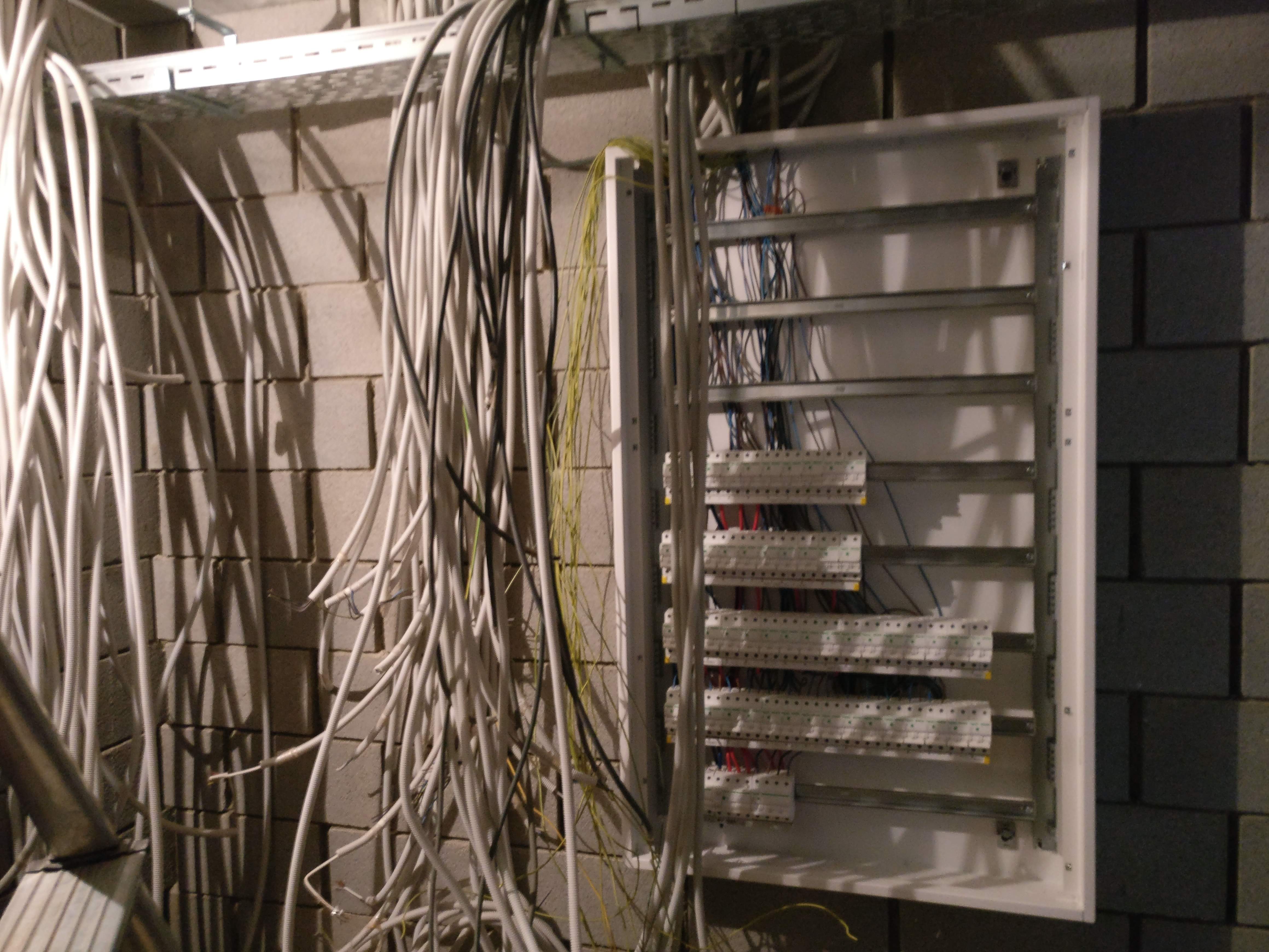
Be sure you have a consistent labelling scheme while pulling all of the cable. Looking back at these pictures, I think it is a bit of miracle I did not miss anything …
Terminal clamps
Besides from labelling the cables during the pulling of the cables, I also did use terminal clamps, like the WAGO rail-mount terminal blocks. On one end of such a block, you have one or more terminals where you can connect your wires. The other end on this block can then later be used to connect whatever you need.
The next figure details the terminal clamps I did use, the WAGO TOPJOB S 2003-7642.
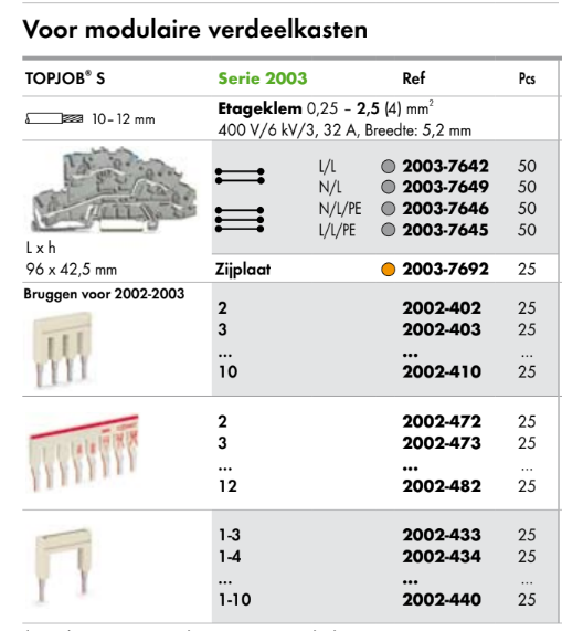
The details include the nominal voltage and current ratings, wire gauges, the physical width of the clamp itself, etc. The lines next to the clamp indicate the different clamp variants available. The first 2 variants are 2 “stories” high (2 electrical connections on a single clamp) whereas the bottom 2 feature 3 “stories”.
Each story represents a single electrical connection, isolated from the other stories. The number of stories all have to do with saving space inside the cabinet: 2 stories really mean you need only half the amount of clamps. Additionally, since most mains voltage wiring is for single phase electrical connection, you can group the phase and neutral wire in one such clamp.
Aside from the first row indicating the details about the terminal clamp, the figure also details many different variants of jumpers available. These jumpers can be placed in the middle ends of the clamps and provide a connection between the different clamps, which facilitates making electrical parallel connections.
Functionally, these terminal clamps does not do all that much. In terms of costs, a single block is not that expensive but since the amount of blocks you need quickly adds up, so do the costs. Nonetheless, I would still highly recommend it to keep a clear overview while inside of your cabinet.
Relays
The next picture shows 2 DIN-rails with all of the terminal blocks for my lights.
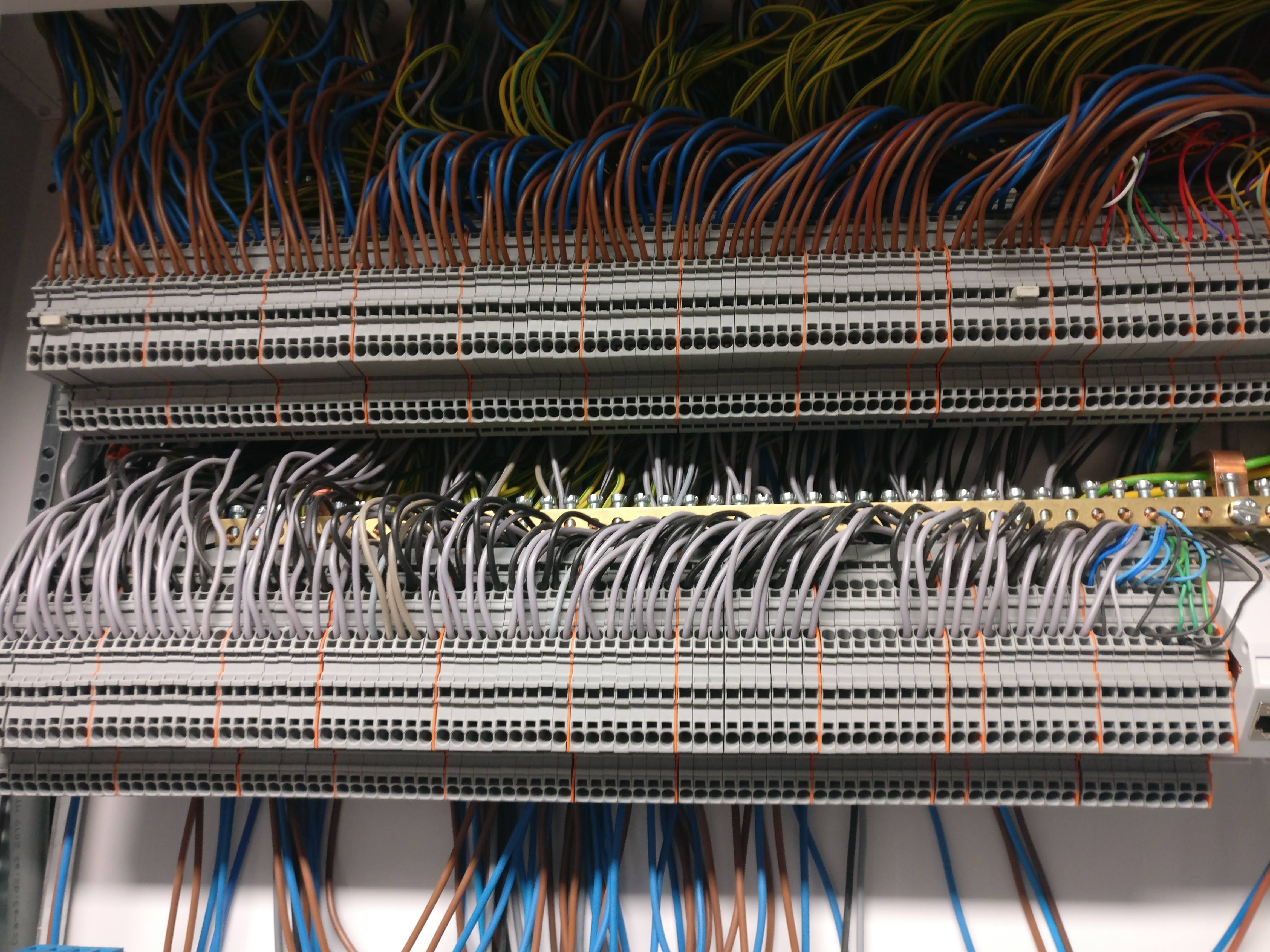
- top row: termination of phase (brown) and neutral (blue) wires.
- bottom row: termination of 2 more wires which I intend to use as a [DALI] bus1; DALI+ (grey) and DALI- (black).
- jumpers: middle of terminal blocks
- orange spacers: each set of blocks between these spacers represent a single electric circuit. This makes it easier to map the one-wire diagram to the actual wiring inside the cabinet.
- green / yellow wires: these are terminated separately on the copper bar (visible between the two DIN rails) and directly connected to the main earth wire.
- two-level terminal blocks: the terminal blocks used here have 2 levels, i.e. the outer 2 terminals are connected as well as the inner 2. A multitude of such terminal blocks exists, ranging for single to multiple levels as well as different functionalities (built-in diodes, resistors, …). Here, two-level terminal blocks were used mostly because of space constraints.
Note that at this point that the wires from the light fixtures in the house were just connected to these terminal blocks: having these blocks there means you can later still have all flexibility for connecting them elsewhere.
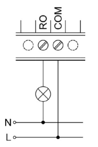
The next part is connecting them to the unit that contains the relays themselves. The unipi relay outputs KB lists all of the details for connecting a single relay:
This connection in itself is not all that complex for a single relay. Since multiple lights on the same circuit are connected to the same circuit breaker, there is the practical concern of how to ensure these are all properly connected in parallel while still maintaining again a good overview. The following picture shows another set of terminal blocks that I did use for this (orange blocks on the left of the unipi unit):
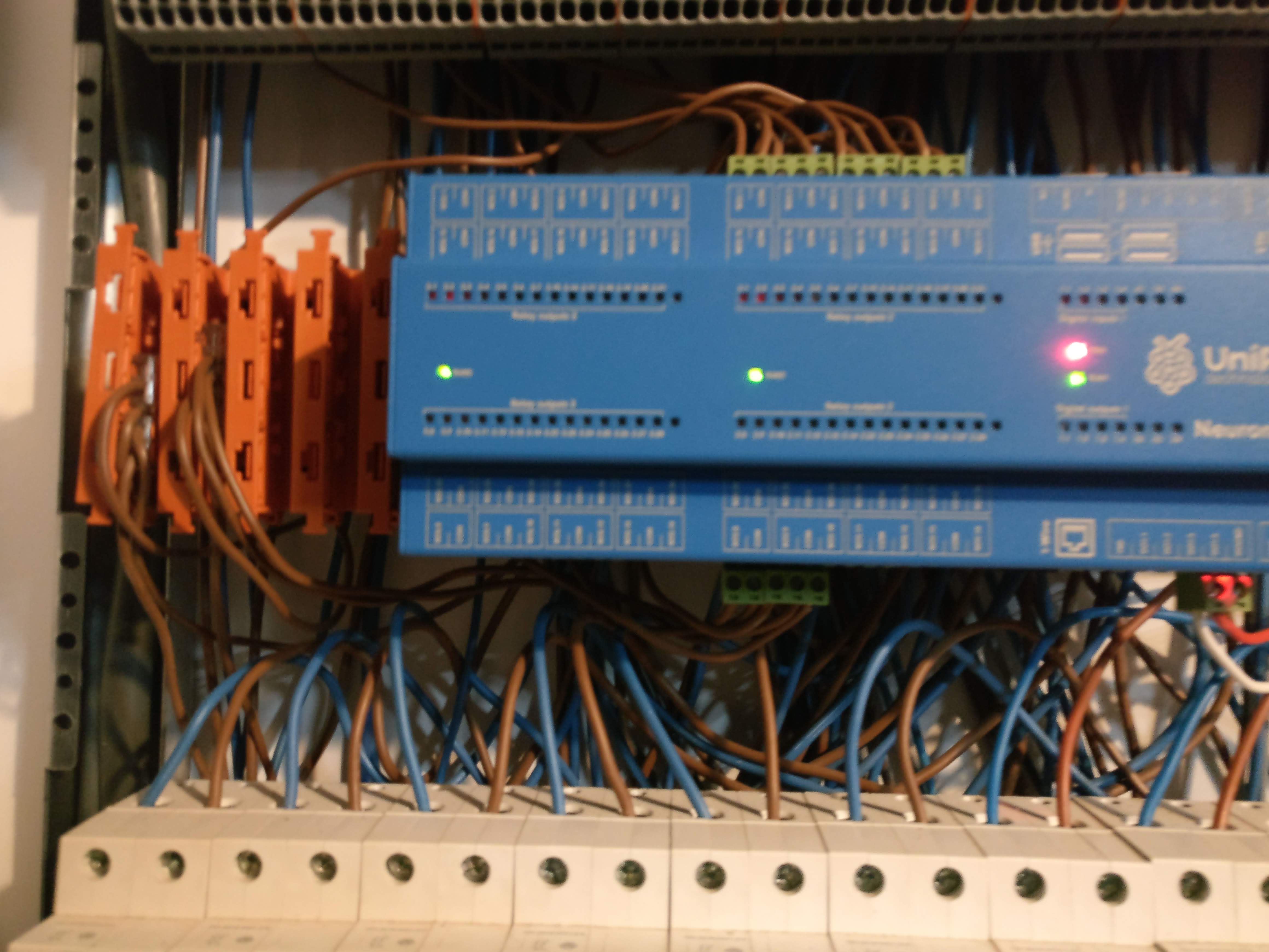
- phase wire (brown): the terminal block holders (orange, left from the unipi module) hold a set of terminal blocks which have one end connected to the circuit breaker, the other ends serve to distribute the voltage to multiple relays.
- neutral wire (blue): since all neutral wires of a single circuit are placed next to each other, these can just be connected in parallel using a jumper.
- relay: each of the lights are connected to “RO” connections coming from the unipi module.
Push buttons
Next to the series of clamps for terminating the cables for the lights, I also did use the same type of clamps for terminating the SVV analog signaling cable:
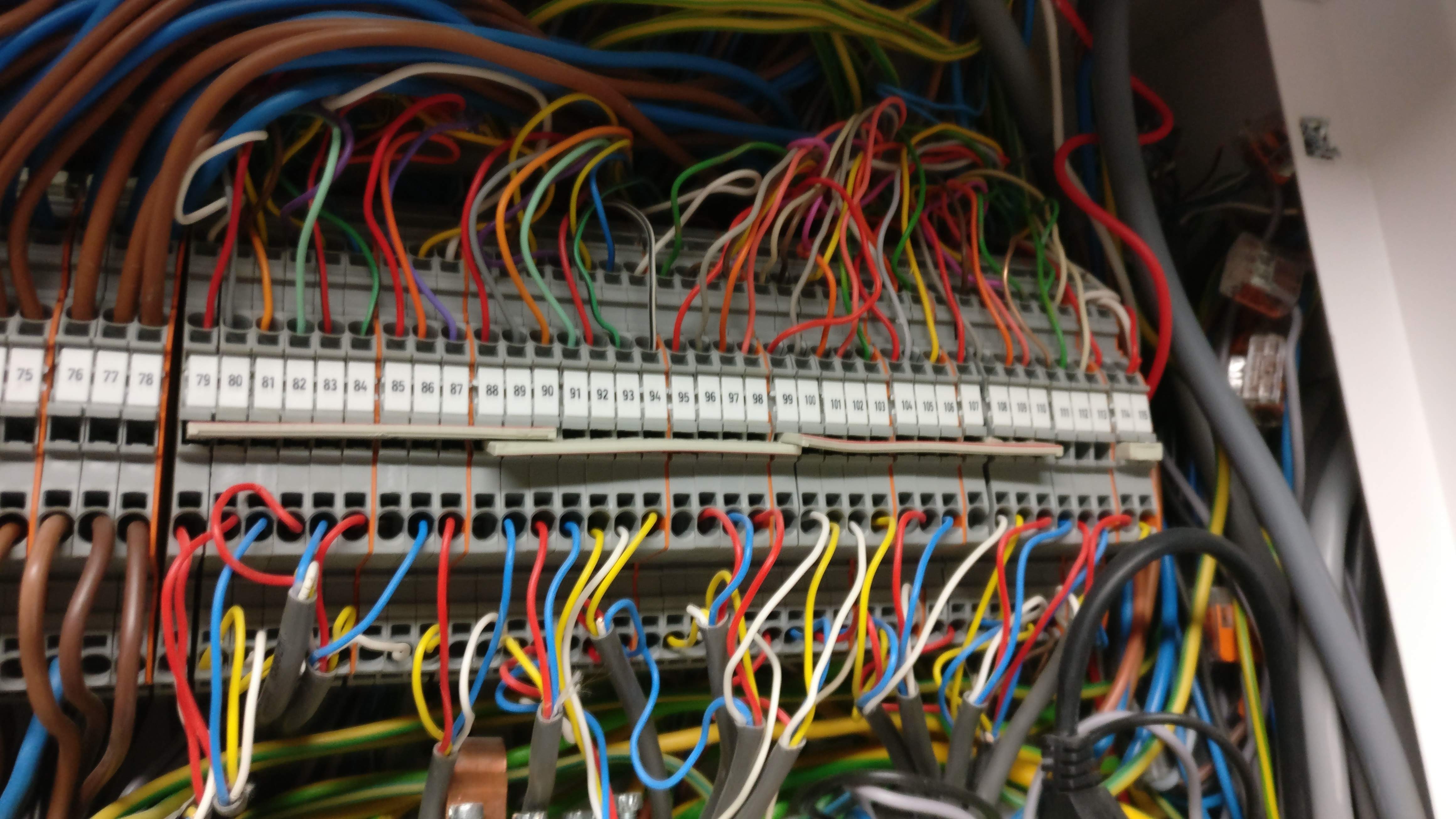
At the top, the incoming signaling cable is terminated. Spacers are placed series of clamps which belong to the same signaling cable run. The bottom part then connects each of the signaling wires to a digital input somewhere lower in the cabinet. In the middle of the clamps, you can see a number of overlapping jumpers. These jumpers have been set up such that they only make an electrical contact in a fixed number of slots, in this case for connecting one of the wires for each cable run to 24V.
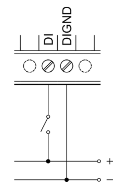
As before, the following image shows the electrical connection from the signaling cable to the unipi digital input unit.
The DIGND corresponds to the ground level of your 24VDC power source.
The DI level is the signaling cable to one of the push buttons.
Pushing a button means the 24V level gets connected to the signal cable and thus giving a DI level of 24V.
For more technical details, consult the unipi digital input KB.
As can be seen from the following picture, making the physical connection between the incoming signal wires and the unipi units is easier than for the relay unit, shown earlier.
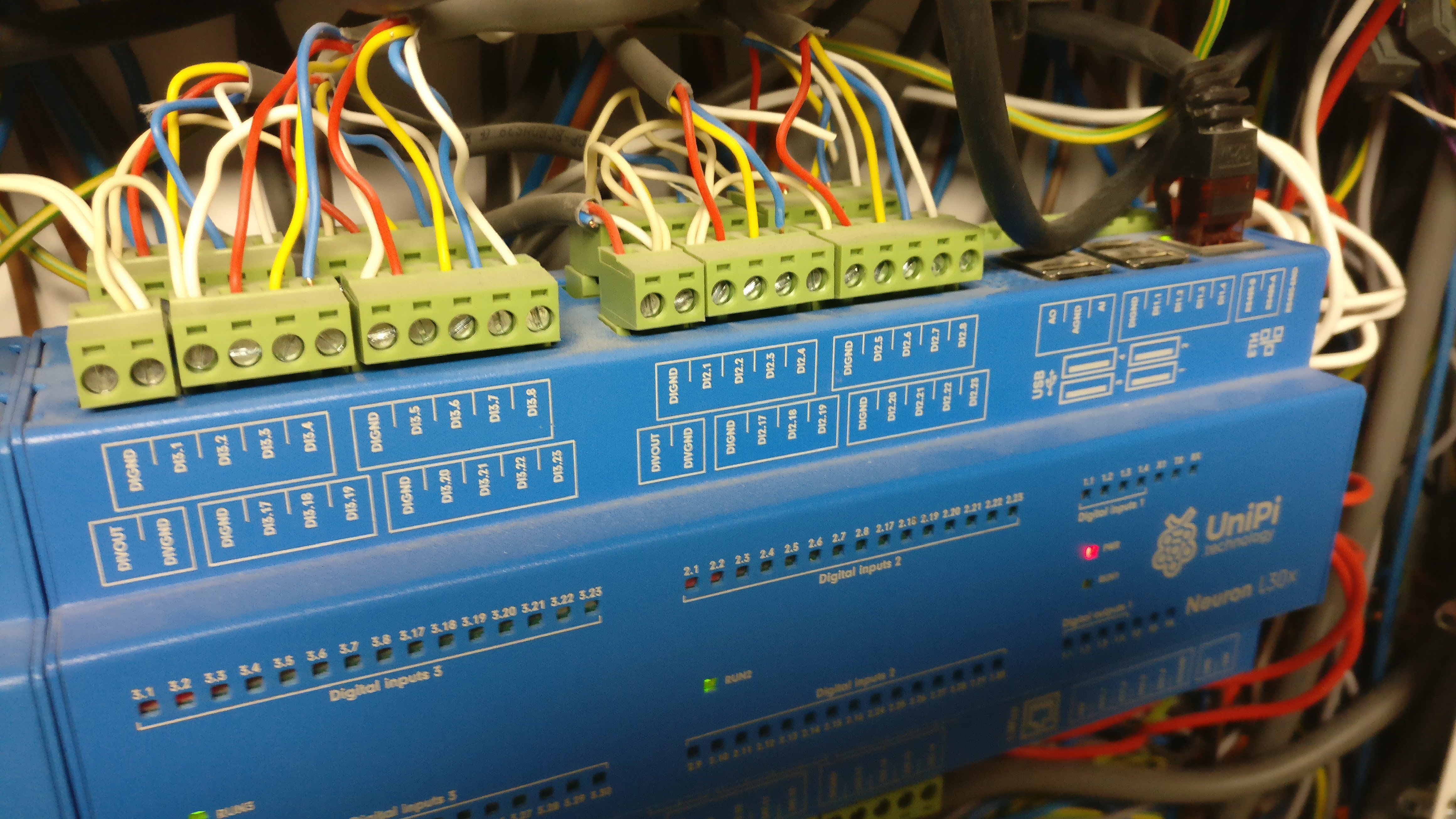
There is no need to have dedicated circuit breakers for the different signal wire cable runs; all of them can run on the same 24VDC power source. Also, since the wire diameter is much lower, the screw connectors can just be used directly to terminate multiple wires and effectively provide electrical parallel connections. Since each of the green screw connectors could have up to 4 signal wire connections and 1 ground level, I did use 4-wire SVV cable to connect them to terminal clamps higher up in the cabinet. Note that I also did use my color coding again here (red / yellow / blue / white).
Closing thoughts
I started this post with some scary pictures of electrical wiring spaghetti.
However, it turns out that with proper planning, schematics and some determination, it was actually quite doable to wire the full cabinet together. Terminal blocks also help a lot in this process: it makes it easier to visually separate everything, removes the need to do all of the wiring in the beginning and enables rewiring at some later point in time.
As before in the series, I did try to explain how to make the connection for push buttons (inputs) and relays (outputs). The connections for the inputs were a bit simpler in the sense that the wiring runs on a safer lower voltage of 24VDC. For the relays, as it runs on mains voltage, there are the additional constraints of the need to add in a circuit breaker for each electrical circuit as well as a higher wire gauge. Consequently, I did some extra clamps to ensure the proper connections.
I did opt for this approach at the time, since it seemed the most simple to me (comes closest to a “classical” setup), the most flexible in terms of rewiring (all wires are within reach) and does not depend on some proprietary, more expensive closed-off bus system. In hindsight, the main disadvantage of such a central star-configuration is the excessive amount of wiring you need to deal with. For costs, you have the additional costs of the wiring material itself. In terms of work, I did do all of the connections myself, so even though I did not lose any money on that, it surely was a very long, laborious process I might rather avoid in the future. With that in mind, at some point in the future I will surely have a closer look at bus-based systems.
DALI is a bus system for digital light control. In theory, you could do full light control with DALI only (removing the need for relay-based control), but this means all of your light fixtures need to be DALI-aware. ↩︎