In previous posts, I did discuss the importance of planning and design as well as details on the physical wires to be used.
Here, I’d like to focus on two types of schematics which are not only very useful, but also mandatory for doing the electrical wiring for a Belgian house: the one-wire diagram and the floor plan.
This post is a part of a larger series of posts on my home automation setup. See the home automation overview post, to learn about the rationale and a description of the other posts!
One-wire diagram
The one-wire diagram is an easy representation of all of the circuits and its related consumers and actors in an electrical installation. As its name implies, it does not show each of the individual wires of the installation but rather how the cables are laid out logically. Initially, this diagram seemed a bit strange to me in the sense that it seems overly simple and does not take the different conductors into account, i.e. the neutral, phases, earth wire … From the point of view of an installer, this diagram actually does make a lot of sense and includes all the details you need.
Note that I no longer make the distinction between push buttons and relays, as was the case in the previous posts.
According to my local regulations, it is not required and even discouraged to include low voltage wiring on the one-wire diagram since it adds to the overall complexity of the diagram. This does have some implications on the representation of light-related circuits though.
In a “traditional” light circuit, a light toggle switch forms a direct mechanical connection to the mains voltage, either through terminating one (one-pole connection) or two (two-pole connection) of the conductors in the wire. Two-pole connections are considered more safe and are even mandatory for humid environments. In terms of the one-wire diagram, the diagram would reflect which toggle switch would connect to which light.
For my setup however, none of the lights are directly connected to the push buttons as these run on their own circuit of 24VDC, which is not on the diagram. Given the push button assignment is controlled by software, it might not even make sense to include them in this diagram. As for safety, since the push button is nowhere near the physical mains voltage cabling, this obviously much safer.
To illustrate, here’s a small annotated (red) part of my installation’s one-wire diagram:
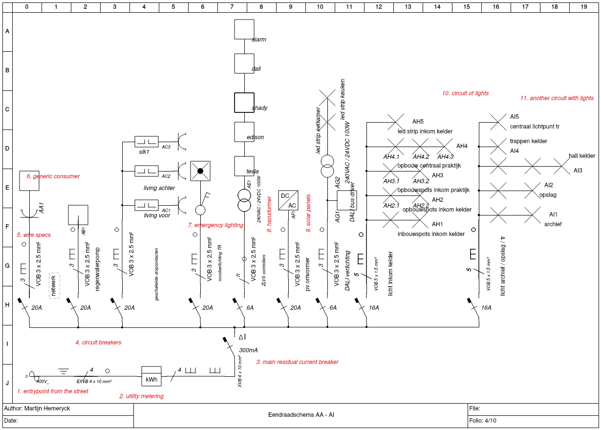
- The bottom left corner holds the entry-point from the street level where the main cable enters the house. In this case, it is a 400V three-phase connection: 3 phase wires plus 1 neutral1.
- Straight after entering the house, the main cable passes through the utility company’s power meter.
- Main residual current device, ΔI=300 mA. This means that if the circuit breaker detects a leakage current ≥ 300 mA, it will automatically shut down the entire installation. Note that for Belgium, the 300 mA is mandatory for the overall installation, for circuits that pass through more humid environments (e.g. bathrooms, toilets), an additional 30 mA residual-current device is required.
- At this level, all of the various circuits are placed in parallel, each with their own circuit breaker.
- Wire specs: note that the circuit breakers need to match the requirements of the wires and the related consumers, as indicated in the physical wires post.
- This level just illustrates two kinds of consumers; first a power socket, then a generic consumer.
- Another example with emergency lighting.
- An example circuit with a 240VAC / 24VDC transformer.
- An example circuit for my solar panel installation.
- This is a circuit exclusively containing lights: each of the branches indicates which lights are wired against the same control point. This means that each of the branches are switched using the same switch, or in this case relay. Note that this does not relate to how they are wired electrically: typically everything is wired in parallel2.
- This is another example of a circuit with lights.
Floor plan
Next to the one-wire diagram, there’s an additional diagram that lays out the circuits and their consumers on a floor plan. Low voltage wiring is also not required for the official floor plan, but it does make sense to have it mapped out somewhere, even if that would be on a separate diagram. The push buttons are obviously also on this plan.
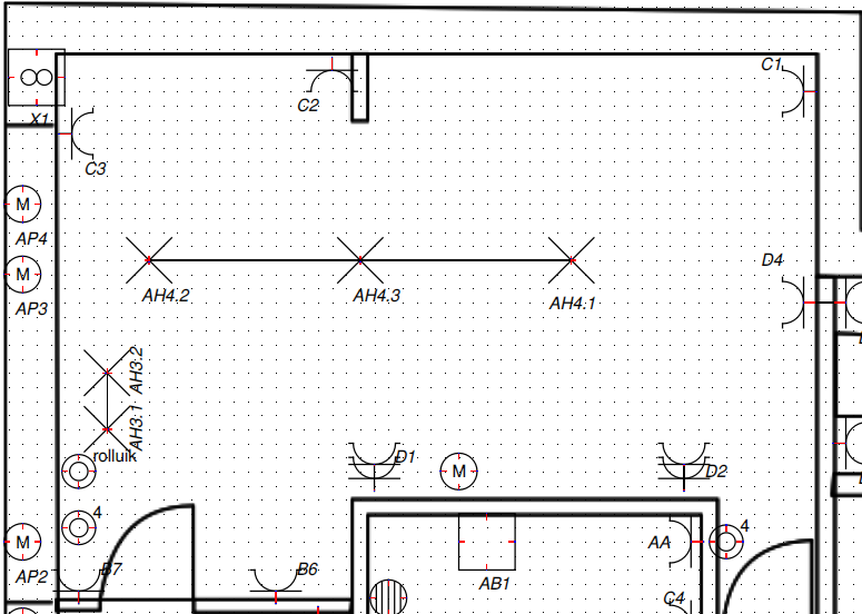
Essentially, it just re-uses the numbering from the one-wire diagram presented earlier, so I won’t discuss these further.
Closing thoughts
Even though these diagrams only represent part of the information, they proved to be really valuable to me along the way:
- planning: since there’s a finite number of consumers you can add to a circuit, it forces you to think ahead of the number of consumers on a single wire run.
- installation: on the construction site, you really don’t want to spend too much time (re)thinking your setup.
- posterity: in case anything breaks down (e.g. a circuit breaker switching off), you just want an easy to digest overview of the whole thing.