In this post, I will take a deeper dive into the bottom layer, the wiring. Different kinds of inputs and outputs can be discussed, but for the sake of simplicity, I will focus on a push button operating a lamp. These components will also come back later on in the series.
This post is a part of a larger series of posts on my home automation setup. See the home automation overview post, to learn about the rationale and a description of the other posts!
I will cover:
- caution: safety first
- principle: operating principle behind a light push button and relay
- conductors: the physical wires and cables themselves
A mandatory word of caution (!)
This post will touch a number of points where working with mains voltage is required. If you do not have any background in working with electricity, please be sure you get help from a qualified electrician. Also, some of the details really only apply to my local regulations (Belgium), so make sure you are well aware of your local regulations. Related to this, some of the terminology used might be a poor translation of some term which would have been straightforward in my native language (Dutch). Even though I had a background as an electrical engineer, I still got a local professional electrician involved to ensure the overall safety …
Principle
Relays
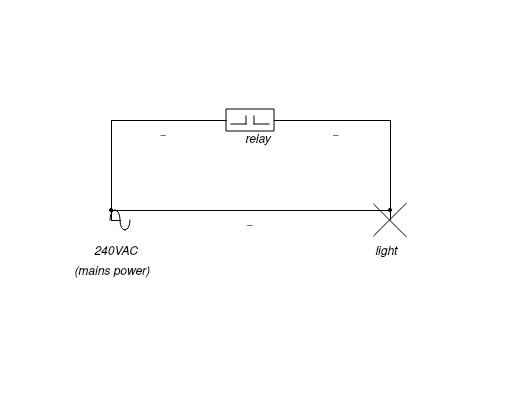
A relay is an electrically operated switch. The voltage over two of its terminals can then control (switch) the voltage over the two other terminals. The control voltage will typically be on a safe, low voltage, whereas the other terminals can carry higher (mains) voltage. You can use it to control any other electrically switched device, e.g. lights or motors.
Push buttons
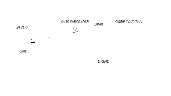
Where the relay serves as the output, the push button, together with a digital input sensor, serves as the input. The push button itself is actually a simple mechanical contact. Pushing the button results in the internal mechanical contact making an electrical contact.
There are two types of contacts: a normally open (NO) contact or a normally closed (NC) contact. Normally open means that the mechanical contact maintains an open electrical contact for the majority of the time, unless the button is pressed. Normally closed is then the opposite situation, meaning a closed electrical contact whenever the button is not pressed. For push buttons, such as those to operate lamps, an NO contact would typically be used. NC contacts make sense for situations where you want to be sure that the electrical contact is always guaranteed, e.g. a sensor for an alarm system. Loss of signal for an NC contact might indicate the sensor has been tampered with.
The voltage used for a push button is typically not mains voltage (240VAC), but rather a lower, safer voltage like 24VDC. Typical digital input sensors such as those found on DIY devices like the arduino or raspberry pi would operate on 5V or 3.3V, respectively. For wiring a house, this is not an option because of the longer line runs and the resulting voltage drop related to the resistance of the wiring itself.
An important thing to consider in the push button - lamp constellation is that the way the push button is used is stateless. Considering the lamp is off, one push would switch the light on. Another push would switch it back off again. Based on the position of the push button itself, you would not be able to tell the state of the light. It differs from a rocker switch in that it only maintains the contact for the duration of the push of the button. While these observations might be rather trivial, for the purposes of modeling them higher up on the stack, they are relevant.
Conductors (Belgium only)
Relays
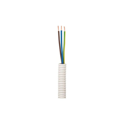
The following image shows a typical tube containing 3 wires with diameters of 1.5mm², fit for lights.
For the cables carrying mains voltage, the following rules are relevant (non-exhaustive see e.g. 1, 2, project huisinstallatie naslagwerk):
- for circuits up to 16A (typically lights), a min 1.5 mm² cross-section wire is to be used
- for circuits up to 20A (lights and / or others like power sockets), a min 2.5 mm² cross-section wire is to be used
- each of the circuits need to have proper matching circuit breakers
- all cables consist of neutral wire, live wire and an earth wire
- color coding:
- neutral: blue
- live: brown
- earth wire: green / yellow
- max 8 consumers (lights, power sockets) per circuit
Keep in mind:
- circuit breakers protect your wires from burning up
- residual-current devices protect living things!
Note that this is only a subset of the rules and pointers to keep into account while doing the physical wiring. Other things to consider are the type of cable (in a plastic tube or as a cable), solid vs stranded wire, stiff vs flexible wire, etc. …
Push buttons
Contrary to the cabling for the lights, the push buttons run on the lower, safer voltage of 24VDC. Consequently, the wire diameter can be a lot smaller and there is no strict requirement on the use of circuit breakers. An additional advantage in terms of safety compared to a more “traditional” installation is that the push button itself is never connected to the consumer on the higher mains voltage.
The following image shows an SVV signal cable, which is typically used in Belgium for analog signaling applications. I did some online research into the international naming for this type of cable, but there does not seem to be any. For the sake of the discussion here however, the characteristics are actually more important:
- small diameters, on the order of 0.8mm²
- solid core, as this makes connecting to the push buttons easier as they mostly have screw connectors
- multiple wires in 1 cable (as shown in the picture). These cables mostly come with either 4, 8, 12 or 16 wires.
- visually clearly differing wires, i.e. highly contrasting colors for the wires
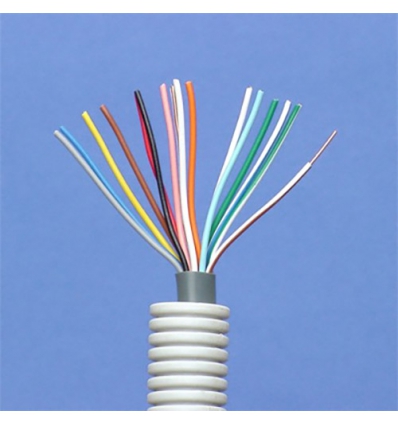
The idea of having this multitude of wires in one signal cable is that you would ideally need one cable run for e.g. the push buttons for one floor. Each push button contact then uses one of the wires of the signal cable. Apart from the push button contacts, you also need to reserve one of the wires for the positive level. Essentially, the push buttons thus internally connect 1 signal wire (on ground level) to the common positive level – which can be detected by your digital input readout.
As a side note, some manufacturers also have push buttons with a built-in LED light. If you want to provide power to that LED, you would also need to reserve an extra wire for that feature.
Concerning the various colors available in the signal cable, I did find it useful to have a fixed order in which to assign them to the different inputs. I would always use the red wire for the positive (24V) level. The remainder of the wires would then be assigned according to the colors on the visible electromagnetic spectrum. For example, you could go from black, grey, brown, orange, green, blue, … all the way to white.
The following image shows the wiring diagram for a simple NO push button from Niko, a Belgian manufacturer of electrical switches and sockets.
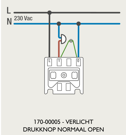
The diagram indicates the push button can be used to switch voltages up the 230VAC, but since we’re only interested in for the signaling application, it might just as well be a lower voltage. Also visible is the optional LED light.
Closing thoughts
The focus of this post was first to describe the basic principle of some key components, the relay and the push button. I did want to highlight what exactly they are and also how the operating principle relates to the modelling higher up in the stack, e.g. the fact that I mostly consider the push button to be stateless.
The second part of the post dealt with the details of the physical electrical conductors connecting to and from these components. Relays, for lights, use 3 x 1.5mm², whereas higher loads require a higher wire gauge of 3 x 2.5mm². The push buttons can use a lower wire gauge of e.g. 0.8mm² since you would run these on a safer, lower voltage of 24VDC. While the regulations pertaining to the wiring are specific to my country’s regulations, I still hope someone else might learn from it!
Finally, always keep safety into account! Even you feel you are really knowledgeable, I still think it was an added value for me to involve a local professional electrician to get proper hands-on advice.